![]()
The Wolfhart Engine
- an advanced two stroke rotary ball piston engine -
Physicist Wolfhart Willimczik

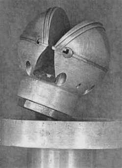
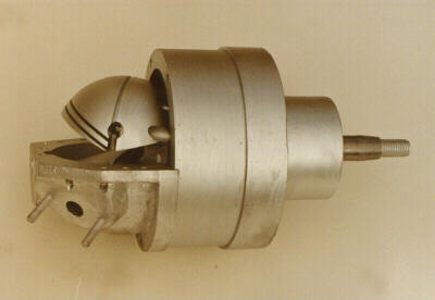
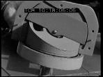
The movement of the piston is recognizable.
(One part of the housing and the wall in the middle are removed. Second kinematik version.)
This was the first model
Drawing taken from German Patent Specification 2519911 and GDR-Patent 113788 of 7.11.1974
Legend:
|
1 - rotary piston |
2 - rotary cylinder |
3 - housing |
|
4 - spherical combustion chamber |
6 - inlet |
7 - exhaust |
|
8 - air intake |
9 - rotary cooling fins |
10 - air outlet |
|
12 - dividing wall |
15 - piston ball bearing |
16 - working chamber |
A spherical piston rotates in combination with a spherical housing, whereby the rotational axes
alone incline towards each other slightly, not unlike a cardan joint. In the process, “strokes” are created within the rotational system, which
are employed to produce periodic volumetric change in working chambers. Two such symmetrical working chambers arise in diametrically opposing sides of
the spherical piston, in sections cut out of the sphere like wedges removed from an orange, one on each side of a smooth dividing wall that extends
into these areas and which is firmly anchored to the casing (external cylinder) that also rotates as part of the system.
Construction:
The spherical piston with the excess for the wall and piston rings.
Kinematics:
In order to understand what goes on inside this device, we will have to take a look at the rotating system. Try to
imagine yourself rotating along with the cylinder rotor. You will observe a swiveling or tumbling motion of the sphere-shaped piston in the
sphere-shaped cylinder. The piston moves back and forth at periodic intervals right up to the dividing wall, while simultaneously swiveling lengthwise
to it. It carries out a tumbling motion that can be differentiated into two pivotal motions occurring vertically on top of one another. One of these
creates the desired stroke motion in the rotating system, the other enables asymmetrical timing. This engine has the kinematics of a single-rotational
engine with the centers of gravity of both rotating parts are at rest. In the coordinate system
at rest there are, in the case of this engine, no to and fro motions. The stroke motions exist only in the co-rotating, body-fixed coordinate system
and generate no oscillating inertial forces. Consequently, this engine produces no vibrations
resulting from oscillating inertial forces. (Consideration of the sealing components is for
the time being left aside as this would go beyond the scope here of general descriptive purposes.)
Two rotors turn, one nested in the other. Contact between the two
occurs via the sealing components. The sliding speeds arising through the motion of both parts tumbling in opposing directions in the co-rotating
system are in fact low. Accordingly, high revolutions per minute are possible (more than 20,000 rpm). Centrifugal and other inertial forces are
however present and may affect particular sealing components at very high speeds.
Seals:
Many a trial of a new principle has come to grief as a result of
seals failing to do their work properly, which is why finding a viable and durable solution was paramount in this instance. The most judicious choice
continues to be for piston rings. They do not provide absolutely impervious barriers, but are serviceable since pressure in the cylinder need only be
briefly maintained. (The more revolutions per minute, the more negligible the leakage factor becomes, as it can be regarded as a time
constant.)
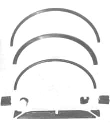
The engine’s
seals
I used 2 compression rings and 1 oil-ring on each piston.
For these reasons, at the circumference of the spherical piston I
use sections of piston compression rings, oil control rings and oil scraper rings respectively, at whose ends minute spaces perform the function
ordinarily fulfilled by the ring gaps. At the center of the sphere, a straight, swivel-mounted elongated seal, (11) pivots up and down from its own
central point at right angles to and in gliding contact with the dividing wall, (12).
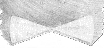
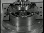
5. Here the
butterfly-winged signs of abrasion caused to the dividing wall by the central seal are clearly visible, reflecting the lateral pivotal motion of the
piston along the dividing wall; also the blackening of the dividing wall as a result of combustion can be detected.
Initially, I employed pointed seals, which has been not robust
enough. I was also disadvantaged through not having proper machine tools at my disposal for the manufacture of parts to the degree of the required
exactitude. I thus next intended to compromise by attempting to use semi-circular seals, which are more robust and able to withstand forces easier.
But this was not to come about, as the SSD was once more directing events...
Lubrication:
As is the case with a standard four-stroke engine, an oil bath is
situated behind the piston, which in turn is fitted with oil scraper rings. Here, attention must merely be paid to ensuring that the oil gathers
externally, because of the rotation. In fact, if outlet ports are placed in this area for the oil, an oil pump can be potentially dispensed with.
Otherwise, oil that is pumped into the center also carries heat from the interior to the exterior, which in turn can be utilized for cooling purposes.
Cooling:
Plain and simple forced air lends itself as a cooling system here.
There are cooling fins attached to the outside of the cylinder rotor that simultaneously act as fan blades. Cooling air is sucked in at the
rear and through channels, (8) inside and blown out through holes, (10) in the housing, (3). (An oil circulation system could also be brought in for
cooling purposes.) A water-cooling system would not be so easy to bring about, but would also be feasible. The manner of cooling depends on whether
the intention is to use the engine to power a lawnmower or a racing car.
Operation and Timing:
The drawing refers to a normal two-stroke process, i.e., one working chamber functions as the charge pump, the other as the engine. Air reaches the charge pump after passing through a port, (6), and is then compressed into the side of the engine via ducts (not visible) - after the outlet, (7) has been closed by the piston and piston rings. Through the swiveling motion of the top edge of the piston this is achieved easily, with the engine developing asymmetrical timing as a result, similar to that of a standard four-stroke engine. This is a great advantage over a normal two-stroke engine. The gas is then fired in the sphere-shaped combustion chamber, (4). Near the bottom dead center, the outlet is again opened and then shut again, then the cycle,,,, takes place, and so on.
The ignition voltage is transferred here through non-contact, which is unproblematic. (On
the contrary, it increases the effectiveness of the spark plug.) By virtue of the better timing diagram and the significantly higher volumetric
efficiency – the “crankcase pump” here having almost no dead volume – a single combustion stroke here produces more power than is the case
with a standard two-stroke engine, for which reason the engine output per unit of displacement here is higher. Moreover,
the number of revolutions per minute can be increased even more, the bearings not being subject to the otherwise high inertial forces, which in turn
raises the engine output per unit of displacement. It would thus be not only a prime mover for lawnmowers and standard motorcycles and cars, but also
a high-performance engine for racing drivers.
For standard cars, the engaging/disengaging of individual cylinders would be more easily
achievable, since they are anyway connected to each other via cogs, gear wheels or similar means.
Other operations corresponding more to those of a turbine would also be feasible.
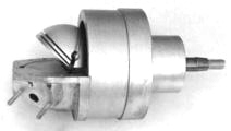
Different positions of the piston
(The wall etc are removed)
I invented this engine in the 1960s in direct competition to the Wankel engine being developed at the time. Comparison to a standard reciprocating piston engine of that era is therefore not made here. If my rotary engine were to be compared to today’s versions of standard piston engines, I would do so using several new principles I have developed since my original type. These operate with asymmetrical control diagrams and direct lubrication, as in my US patent 6,152,014
Comparison Between
Wankel and Wolfhart Engine
|
Wankel Engine |
Wolfhart Engine
|
Rotary Piston Engine
The center of gravity of moving parts (piston) rotates in a
circular path |
Rotary Piston Engine
The center of gravity of moving parts (piston and cylinder) is at
rest |
|
Three-chamber four-stroke operational principle with asymmetrical timing diagram |
Two-chamber two-stroke operational principle with asymmetrical timing diagram |
|
Linear sealing with pointed sealing strips |
Sealing via piston rings (segments) and flat sealing strips |
|
High sliding speeds of sealing strips |
Low sliding speeds of sealing strips |
|
Fuel needs oil added to it |
Direct oil lubrication as with standard four-stroke reciprocating engine |
|
High revs per minute not possible |
High revs per minute possible |
The report on my inventions 1975

There my invention runs as a
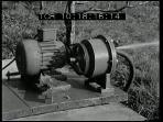

water pump vacuum
pump compressor
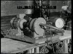
Video clip from 1975 “News from Science and
Technology”
RealMedia (rm) 1,8MB
or Media
(avi) 4,2MB and smaller picture
My TV debut along with my machine was to serve as a foretaste of a longer report on the invention intended for broadcast at a later date. This however never materialized. My engine was never seen. I was subsequently expelled from the Academy of Science (layoff) , jailed and divorced by coercion and all my inventions barred as “a matter of state security". My manuscript written in 1975 remained unpublished. The only recorded views concerning my engine still extant.

Physicist Wolfhart Willimczik
info@WolfhartIndustries.com
©2014 All rights reserved
WolfhartIndustries
videos of my inventions
tests of the latest Wolfhart pump
the ideal principle for the water hydraulic and reverse osmosis
the ideal fuel pump
the ideal pump for waterworks and the smallest Wolfhart pump
the ideal principle for oil-free compressors at high pressure
other Wolfhart rotary piston technologies
Publications:
My latest US-Patent 6,152,014
My invention in "World Pumps"
My patents and other publications
Links to Wolfhart technologies:
http://www.allstar.fiu.edu/aero/WOLFHART.htm
http://www.animatedsoftware.com/pumpglos/wolfhart.htm
